Claudio Gandolfi - MDD (Multi Delays Diffraction)
Mail: info@claudiogandolfi.it - This is a script free web site - Home
Progetto MDD Back Load 21BL12


Per il primo carico posteriore 21BL12 ho scelto l'altoparlante HX135 per superare il limite di altoparlanti piccoli come il 3FE25. Non possono riprodurre elevali SPL alle basse frequenze, gli spostamenti richiesti al cono arrivano rapidamente al limite dell'Xmax con un altrettanto rapido aumento della distorsione e il rischio di danneggiare l'altoparlante. Nel progetto 22C71L8 si riproducono i 40 Hz ma solo se non si superano i 90 dB. Con altoparlanti più grandi si usano più guide d'onda in guaina spiralata e di maggiore sezione. Stabilita la frequenza minima con lunghezze di 2, 3 o 4 metri il volume totale occupato è proporzionale all'area dell'altoparlante. Vale la pena studiare la distrbuzione nel contenitore predisposto di 15, 30 o 50 metri di guaina spiralata, non è semplice come avvolgere del filo elettrico.
For the first 21BL12 rear load I chose the HX135 speaker to overcome the limit of small speakers like the 3FE25. They cannot reproduce SPL elevations at low frequencies, the displacements required at the cone quickly reach the Xmax limit with an equally rapid increase in distortion and the risk of damaging the speaker. In the 22C71L8 project 40 Hz is reproduced but only if it does not exceed 90 dB. With larger loudspeakers, multiple waveguides in a spiraled and larger cross-section are used. Once the minimum frequency has been established with lengths of 2, 3 or 4 meters, the total volume occupied is proportional to the area of the loudspeaker. It is worth studying the distribution in the prepared container of 15, 30 or 50 meters of spiral sheath, it is not as simple as winding electrical wire.
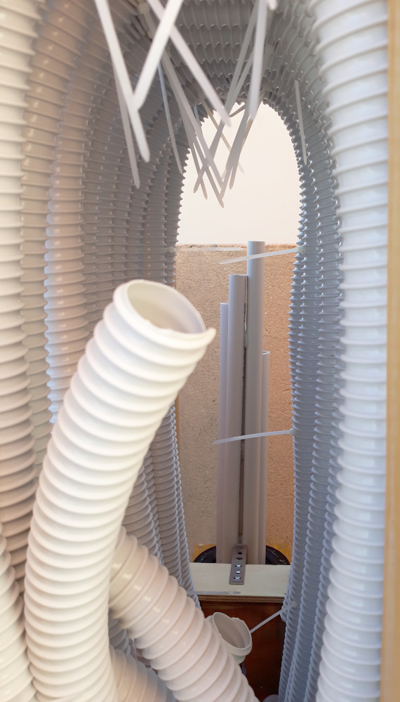
La progettazione del caricamento posteriore con tecnologia MDD è semplice, più complessa è la realizzazione. Per comodità uso le guide con la stessa sezione (con sezioni diverse si complicano i calcoli). Scelta la sezione, il numero di guide si calcola in modo che il totale dell'area di tutte le sezioni sia uguale all'area del cono dell'altoparlante. Per l'altoparlante HX135 ho scelto 12 guide d'onda in guaina spiralata per impianti elettrici da 32 mm di sezione. Le guide d'onda (linee di trasmissione TL) possono funzionare come schermi acustici per lunghezze d'onda fino a 4 volte la loro lunghezza. Per estendere verso il basso la risposta in frequenza ho aumentato progressivamente la lunghezza delle guide d'onda, quando con guide d'onda diritte sono arrivato all'altezza del soffitto sono passato all'uso della guaina spiralata per impianti elettrici. La guaina è flessibile e il numero delle possibili forme è limitato solo dalla fantasia. Le guide possono essere avvolte in uno spazio cubico che simuli la forma di molti sub commerciali, se si vuole privilegiare la portabilità. Le guaine spiralate possono essere montate all'interno di muri o mobili, nel baule di un auto, ecc... .
The design of the back loading with MDD technology is simple, the more complex the realization. For convenience I use the guides with the same section (with different sections complicate the calculations). Once the section has been chosen, the number of guides is calculated so that the total area of all the sections is equal to the area of the speaker cone. For the HX135 loudspeaker I chose 12 waveguides in spiral sheath for 32 mm section electrical systems. The waveguides (TL transmission lines) can function as acoustic screens for wavelengths up to 4 times their length. To extend the frequency response downwards, I gradually increased the length of the waveguides, when with straight waveguides I reached the ceiling I switched to the use of the spiral sheath for electrical systems. The sheath is flexible and the number of possible shapes is limited only by the imagination. The guides can be wrapped in a cubic space that simulates the shape of many commercial subwoofers, if you want to favor portability. The spiral sheaths can be mounted inside walls or furniture, in the trunk of a car, etc ....
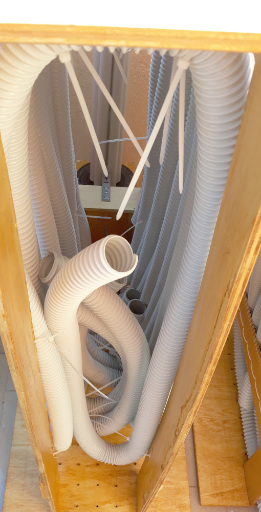
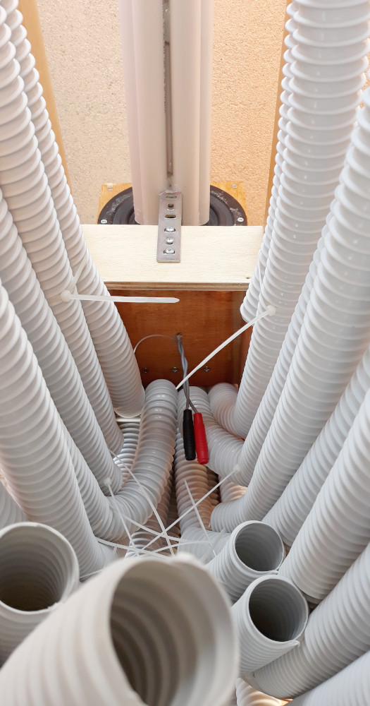
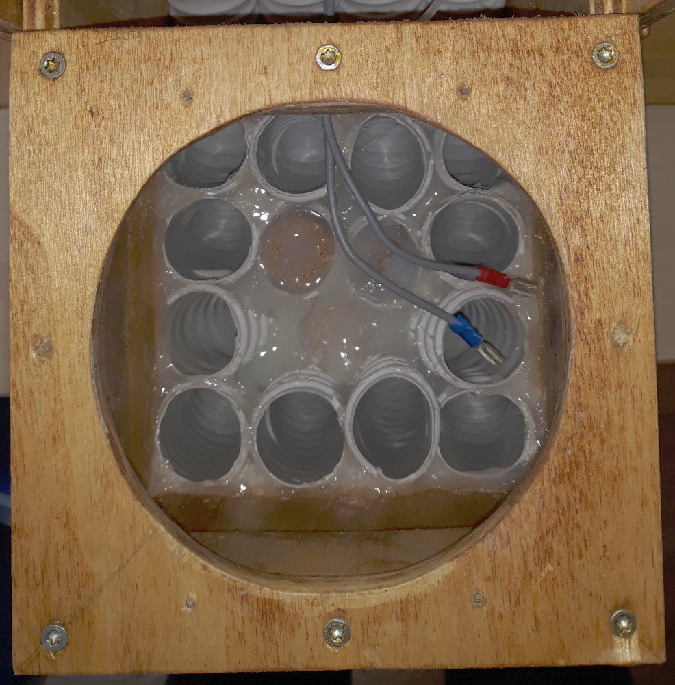
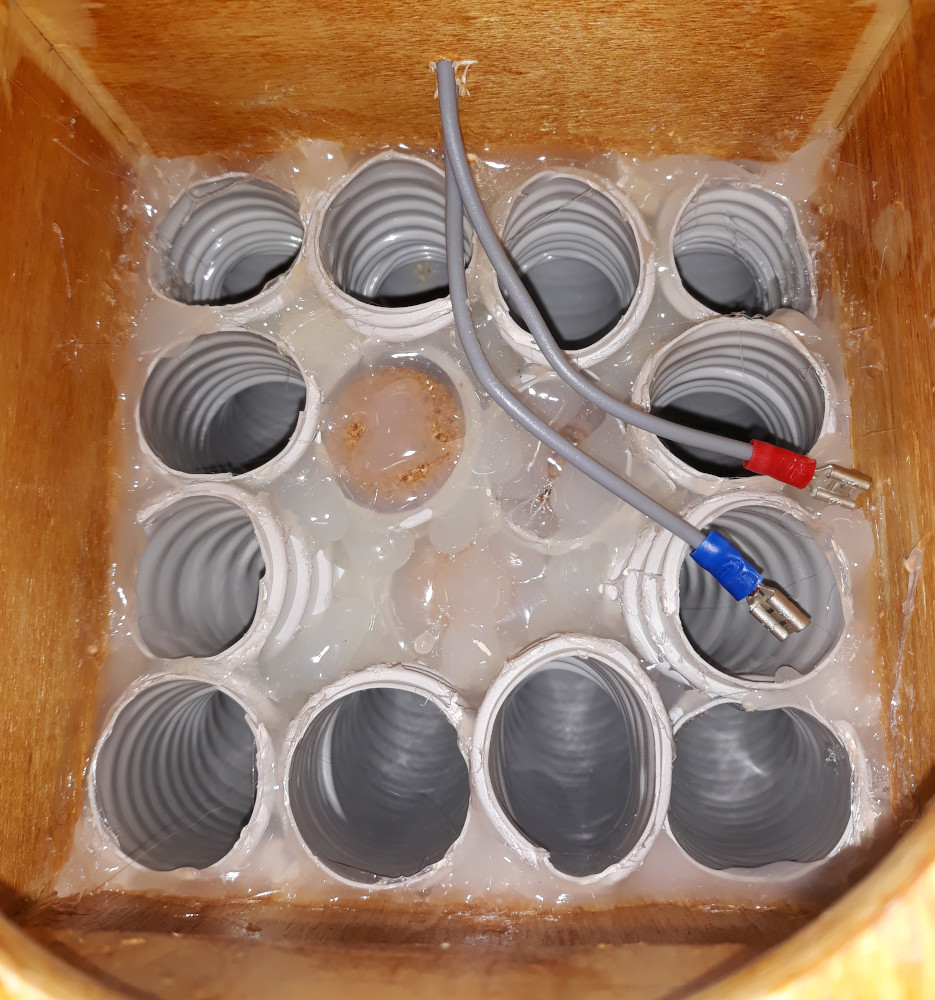
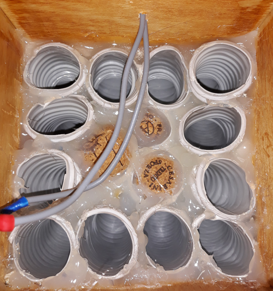
Ho scelto Lmax = 2 * Lmin con la serie logaritmica di lunghezze: 1775, 1880, 1992, 2110, 2236, 2369, 2510, 2659, 2817, 2985, 3162, 3350 mm. L'altoparlante HX135 è montato in orizzontale, sul lato superiore di un cubo (160 x 160 x 160 mm) in legno multistrato aperto verso il basso. La metà superiore del cubo funziona da camera di compressione per l'emissione posteriore dell'altoparlante. La meta inferiore del cubo è utilizzato per raccordare le dodici guide d'onda in guaina spiralata. Le guaine sono fissate sul perimetro del cubo con viti e colla a caldo che fissa garantisce la tenuta d'aria per il funzionamento corretto lelle guide come linee di trasmissione.
I chose Lmax = 2 * Lmin with the logarithmic series of lengths: 1775, 1880, 1992, 2110, 2236, 2369, 2510, 2659, 2817, 2985, 3162, 3350 mm. The HX135 speaker is mounted horizontally, on the upper side of a cube (160 x 160 x 160 mm) in plywood, open downwards. The upper half of the cube acts as a compression chamber for the rear emission of the speaker. The lower half of the cube is used to connect the twelve in spiral sheaths. The sheaths are fixed on the perimeter of the cube with screws and hot glue which fixes ensures the air tightness for the correct functioning of the guides as transmission lines.
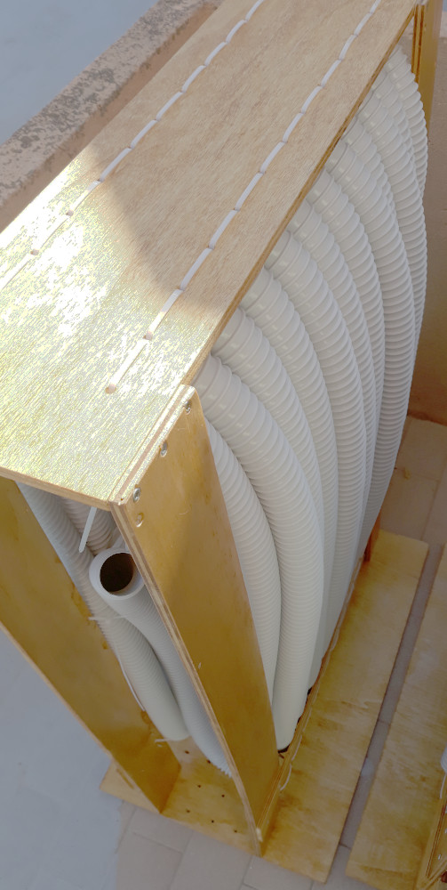
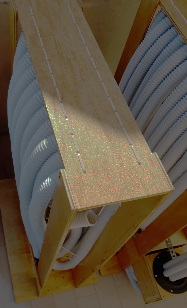
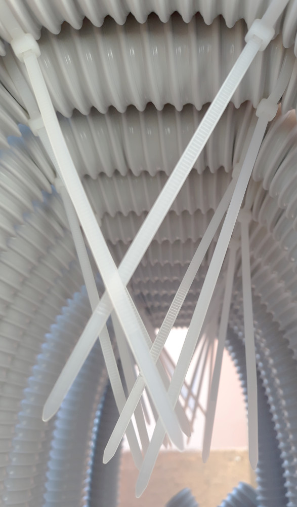
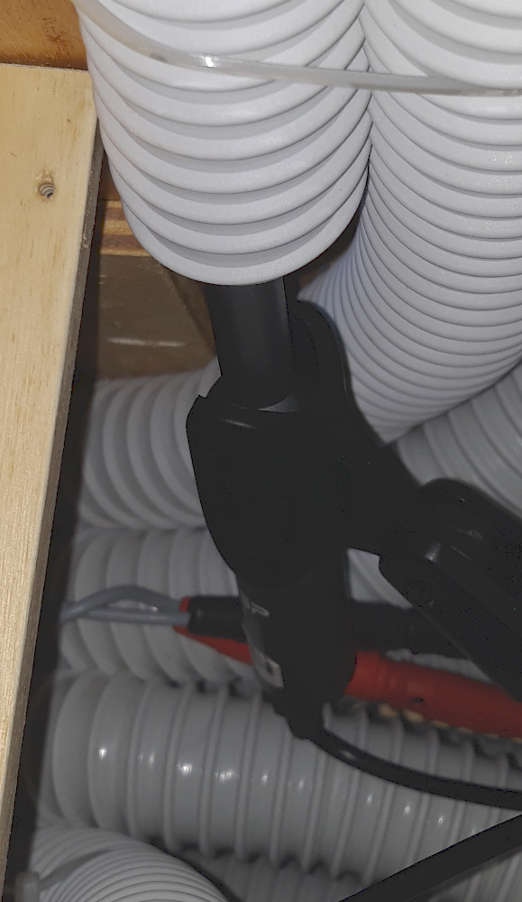
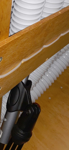
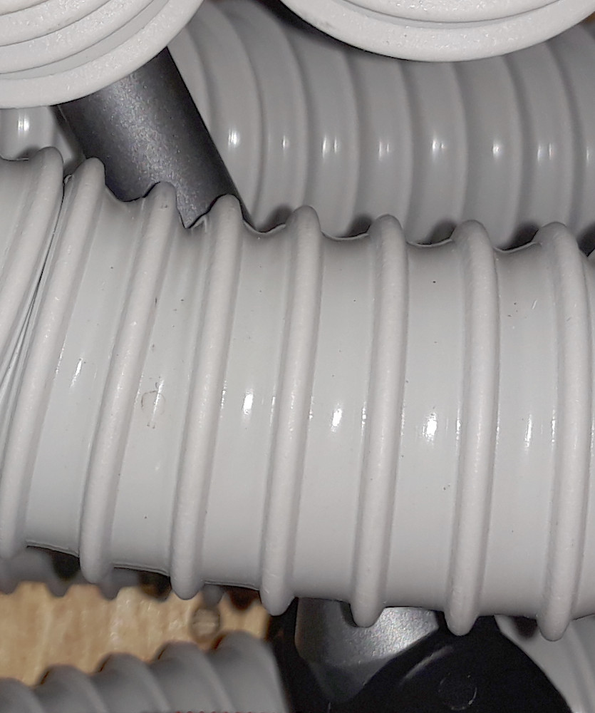
Il cubo in legno e le guide d'onda sono tenute in posizione con un telaio in legno (600 x 1000 mm) come mostrato nelle foto. Nel telaio sono stati realizati fori a distanza di 40 mm per fissare la guaina spiralata con fascette per cavi elettrici. Vicino all'altoparlante sono fissate le guide più corte con l'uscita vicino al pavimento. Sul lato posteriore sono fissate le guide più lunghe con l'uscita progressivamente più alta.
The wooden cube and waveguides are held in place with a wooden frame (600 x 1000 mm) as shown in the photos. Holes have been made in the frame at a distance of 40 mm to fix the spiral sheath with cable ties. Shorter rails are attached near the speaker with the exit near the floor. Longer guides with progressively higher exit are fixed on the back.
La risposta in frequenza di ogni singola guida d'onda presenta dei minimi e massimi a frequenze di risonanza in relazione con la lunghezza della guida stessa. Le risonanze, come la diffrazione acustica, non sono problemi nella tecnologia MDD ma risorse. Utilizzando un'unica guida per la riproduzione delle basse frequenze, è necessario sintonizzarla con il driver utilizzato e posizionare l'altoparlante in un punto adatto nell'ambiente di ascolto. È più probabile che ci sia un buon ascolto con guide di risonanza multiple distribuite su un'intera ottava, si compensano parzialmente tra loro, con l'altoparlante e con l'ambiente di ascolto. Per ogni frequenza esiste un percorso adatto per trasferire l'energia sonora dalla membrana dell'altoparlante al punto di ascolto. Vedi cabinet neutro.
The frequency response of each individual waveguide has minimum and maximum frequencies at resonance in relation to the length of the guide itself.Resonances, like acoustic diffraction, are not a problems in MDD technology but resources. Using a single guide for the reproduction of low frequencies, it is necessary to tune it with the driver used and position the speaker in a suitable point in the listening environment. There are more likely to be a good listening with the multiple resonance guides distributed over an entire octave, they partially compensate each other, with the driver and with the listening environment. For each frequency there is a path suitable for transferring sound energy from the driver membrane to the listening point. See neutral cabinet.
E' possibile studiare un pattern di posizioni di uscita delle guide d'onda che compensi risonanze specifiche dell'ambiente d'ascolto. Non ho ancora provato, ha senso solo in un ambiente dedicato esclusivamente alla riproduzione audio. Il progetto MDD si comporterebbe come come un sub single drive con punti di emissione coerenti distribuiti nello spazio 3D.
It is possible to study a pattern of waveguide output positions that compensates specific resonances of the listening environment. I haven't tried it yet, it only makes sense in an environment dedicated exclusively to audio reproduction. The MDD project would behave like a sub single drive with coherent emission points distributed in 3D space.
Misure MDDHX135 - 21BL12
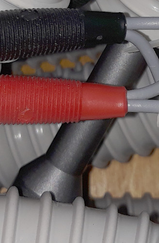
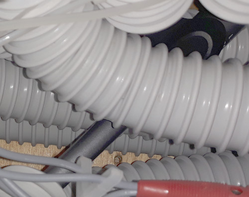
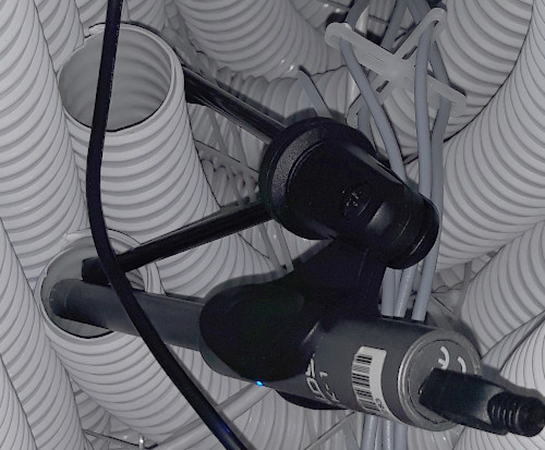
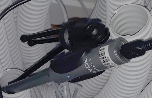
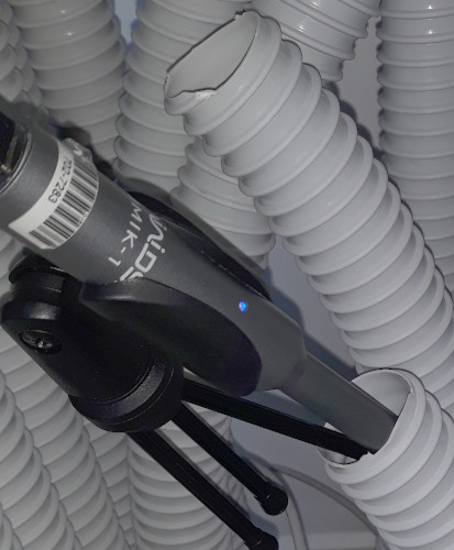
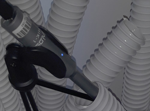
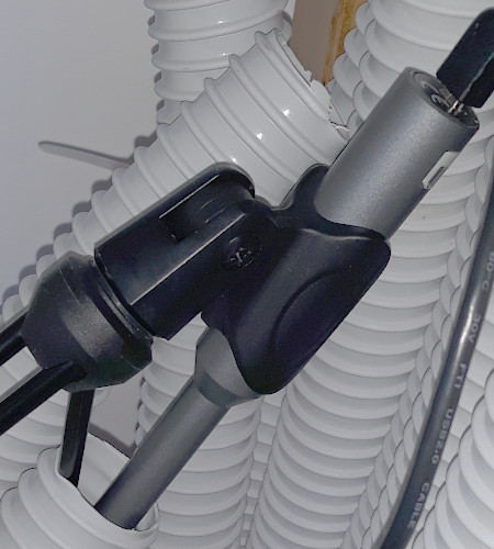
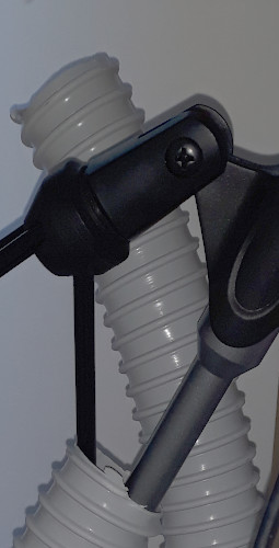
Per queste misure si è posizionato il microfono allo sbocco delle singole guide d'onda e con funzioni matematiche si è calcolato l'andamento medio dei dati rilevati.
For these measurements the microphone was positioned at the outlet of the individual waveguides and with mathematical functions the average trend of the detected data was calculated.
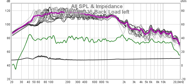
La linea nera in basso è l'impedenza. La linea verde è la risposta in frequenza della cassa acustica MDDHX135 in ambiente. Le linee in scala di grigi sono le misure rilevate con il microfono appoggiato all'interno dello sbocco delle singole guide d'onda rigide. La linea rossa é la media calcolata dalle misure precedenti allo sbocco delle guide d'onda. La funzione mostra che i picchi distruibuiti su un'ottava si compensano.
The black line at the bottom is the impedance. The green line is the frequency response of the MDDHX135 acoustic speaker in the room. The grayscale lines are the measurements taken with the microphone resting inside the outlet of the individual rigid waveguides. The red line is the average calculated from the measurements preceding the outlet of the waveguides. The function shows that peaks distributed over an octave compensate.
Il carico acustico posteriore 21BL7d è formato da tre parti: 1 - la camera di compressione che alloggia l'altoparlante e sostiene le guide d'onda in pvc rigido, 2 - la staffa di supporto a risonanza subsonica, 3 - le guide d'onda in pvc rigido.
The rear acoustic load 21BL7d consists of three parts: 1 - the compression chamber which houses the speaker and supports the rigid PVC waveguides, 2 - the subsonic resonance support bracket, 3 - waveguides in rigid pvc.
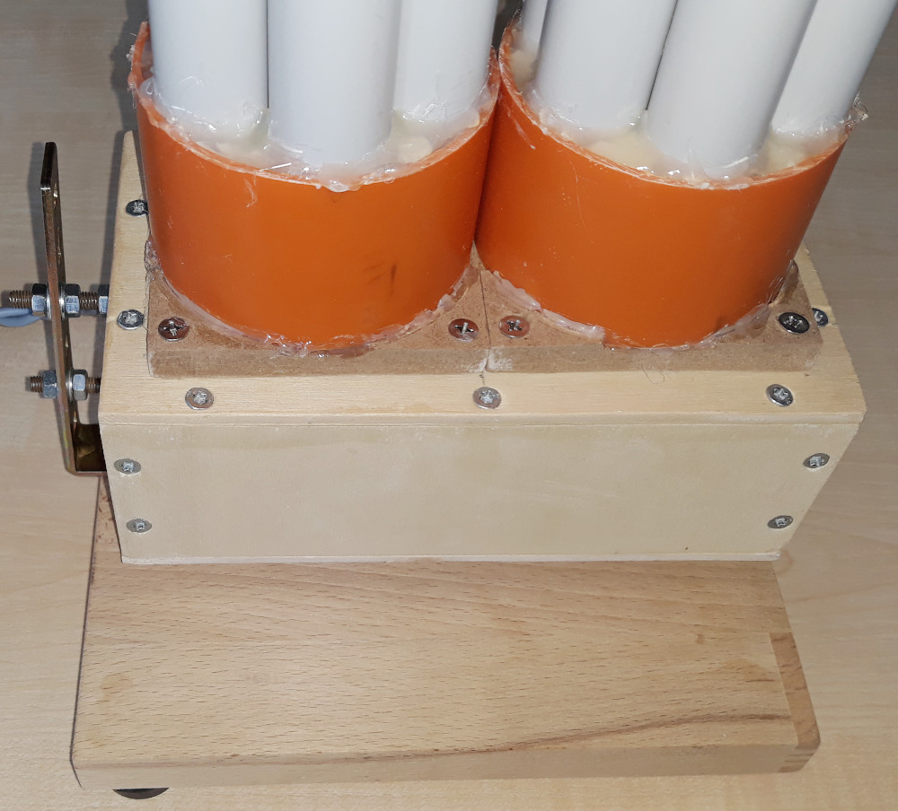
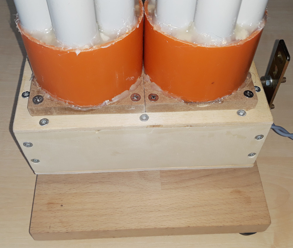
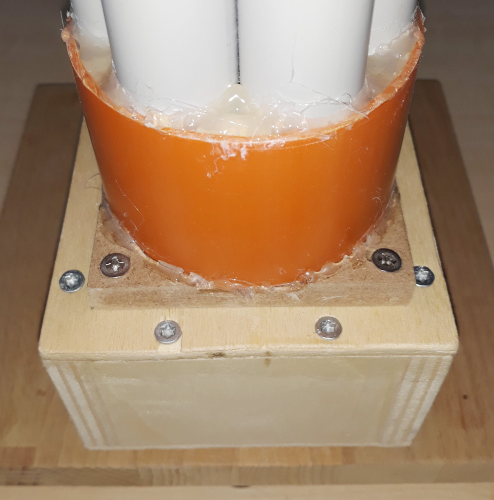
La camera di compressione, ha la forma di un parallelepipedo con la sezione leggermente superiore alle dimensioni interne dell’altoparlante, in questo caso 80 x 57 x 160 mm. La lunghezza è di 160 mm per dare una profondità minima che generi l’effetto 3D distanziando il caricamento acustico posteriore MDDBL in pvc rigido dall’altoparlante. La camera di compressione è in multistrato con pareti laterali da 12 mm e i pannelli superiore e inferiore da 4 mm. I pannelli sono fissati con viti da legno e con i bordi sigillati.
The compression chamber has the shape of a parallelepiped with the section slightly larger than the internal dimensions of the speaker, in this case 80 x 57 x 160 mm. The length is 160 mm to give a minimum depth that generates the 3D effect by distancing the MDDBL rear acoustic loading in rigid pvc from the speaker. The compression chamber is made of plywood with 12 mm side walls and 4 mm upper and lower panels. The panels are fixed with wood screws and with sealed edges.
I fili dell’altoparlante sono ritorti per diminuire le interferenze elettromagnetiche ed escono da lato posteriore della camera di compressione attraverso un paio di fori da 3 mm. I fili sono terminati con banane da 4 mm.
The speaker wires are twisted to decrease electromagnetic interference and come out from the back side of the compression chamber through a pair of 3 mm holes. The threads are terminated with 4mm bananas.
All’estremo anteriore del lato superiore è montato l’altoparlante sotto il foro da 72 mm.
At the front of the upper side, the speaker is mounted under the 72 mm hole.
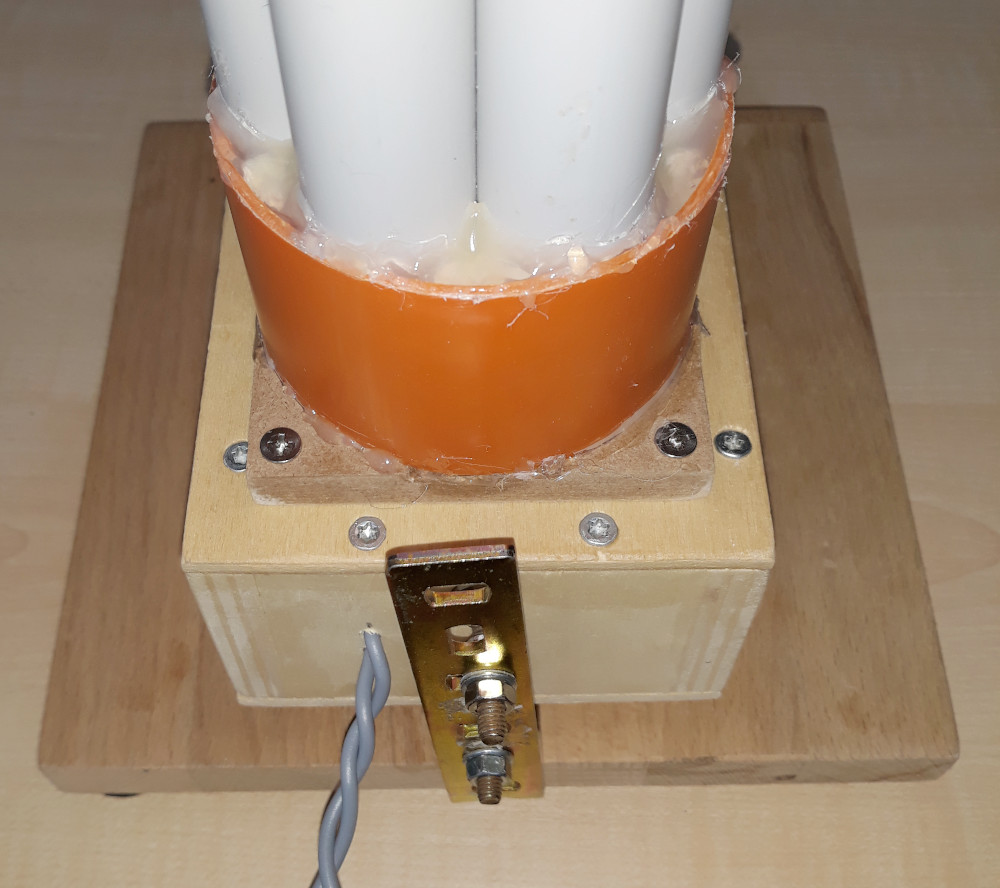
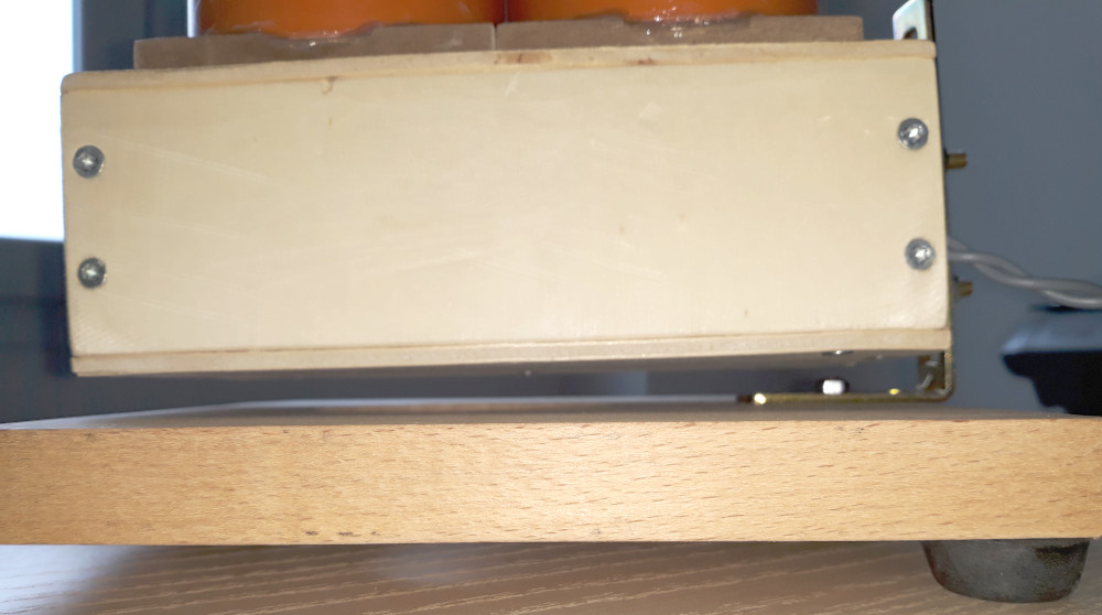
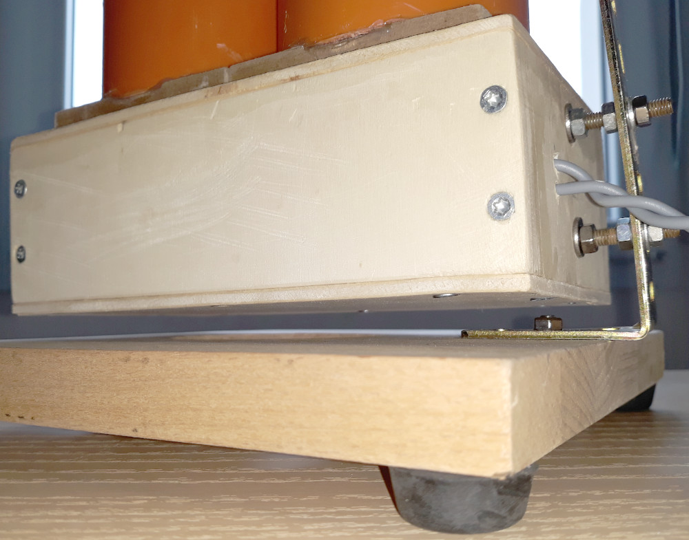
Una staffa in acciaio sostiene la camera di compressione. Ha una sezione di 2.5 x 20 mm e deve essere abbastanza robusta da sostenere pesi di alcuni Kg con leve molto svantaggiose. Le viti M5 e i relativi dadi permetto la regolazione della verticalità della cassa acustica.
A steel bracket supports the compression chamber. It has a section of 2.5 x 20 mm and must be robust enough to support weights of a few kg with very disadvantageous levers. The M5 screws and the relative nuts allow the adjustment of the verticality of the loudspeaker.
La staffa è fissata alla base con una vite M5 che regola la direzione laterale della struttura. La base è una tavola in legno di circa 200 x 200 x 20 mm con 3 piedini distanziatori.
The bracket is fixed to the base with an M5 screw that adjusts the lateral direction of the structure. The base is a wooden board of about 200 x 200 x 20 mm with 3 spacer feet.


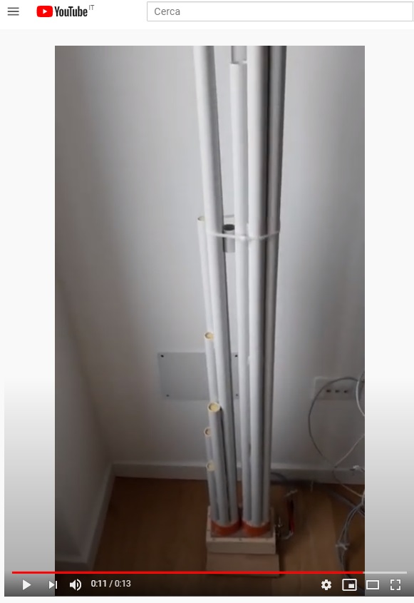
Il carico acustico posteriore MDDBL 21BL7d ha una lunghezza massima di 2000 mm ed è formato da sette tubi circolari in pvc rigido (25 x 1,5 mm) usati negli impianti elettrici. La serie delle sette lunghezze è: 1104, 1219, 1346, 1486, 1641, 1811, 2000 mm. Le guide d’onda sono fissate con viti alla camera di compressione in cui è stato praticato un foro da 72 mm di diametro. Per eliminare le risonanze a λ/2 nel grafico dell’impedenza si sono inseriti dei cubetti in gommapiuma alla fine di ogni guida d’onda.
The rear acoustic load MDDBL 21BL7d has a maximum length of 2000 mm and is made up of seven circular rigid PVC pipes (25 x 1.5 mm) used in electrical systems. The series of the seven lengths is: 1104, 1219, 1346, 1486, 1641, 1811, 2000 mm. The wave guides are fixed with screws to the compression chamber in which a 72 mm diameter hole has been drilled. To eliminate the resonances at λ / 2 in the impedance graph, foam rubber cubes were inserted at the end of each waveguide.
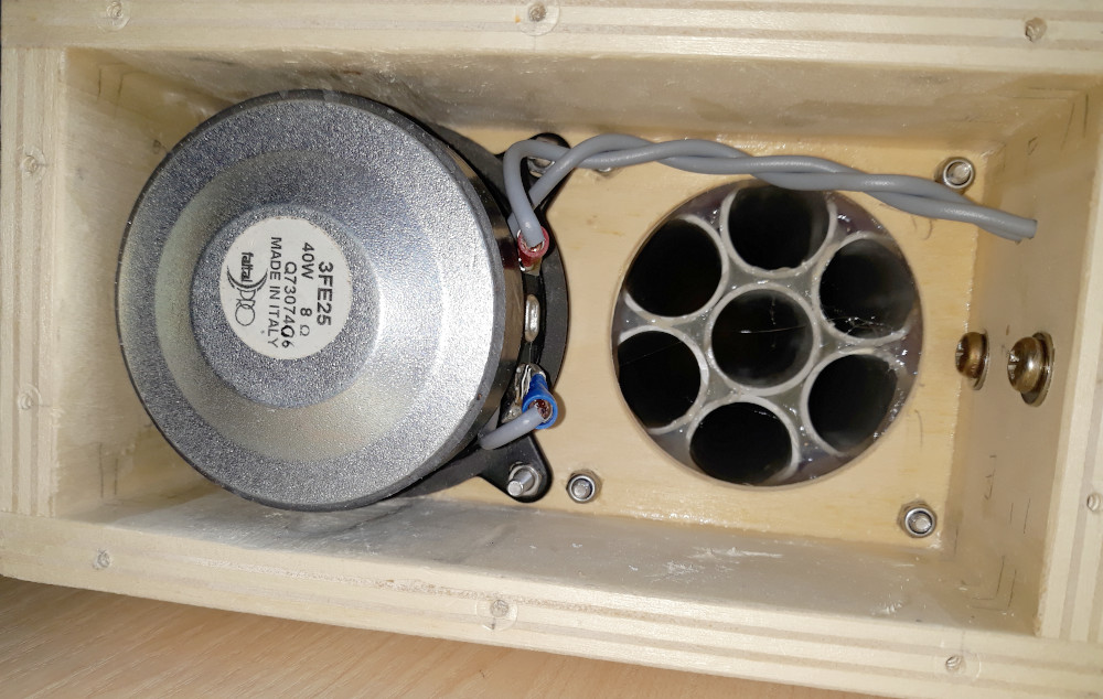
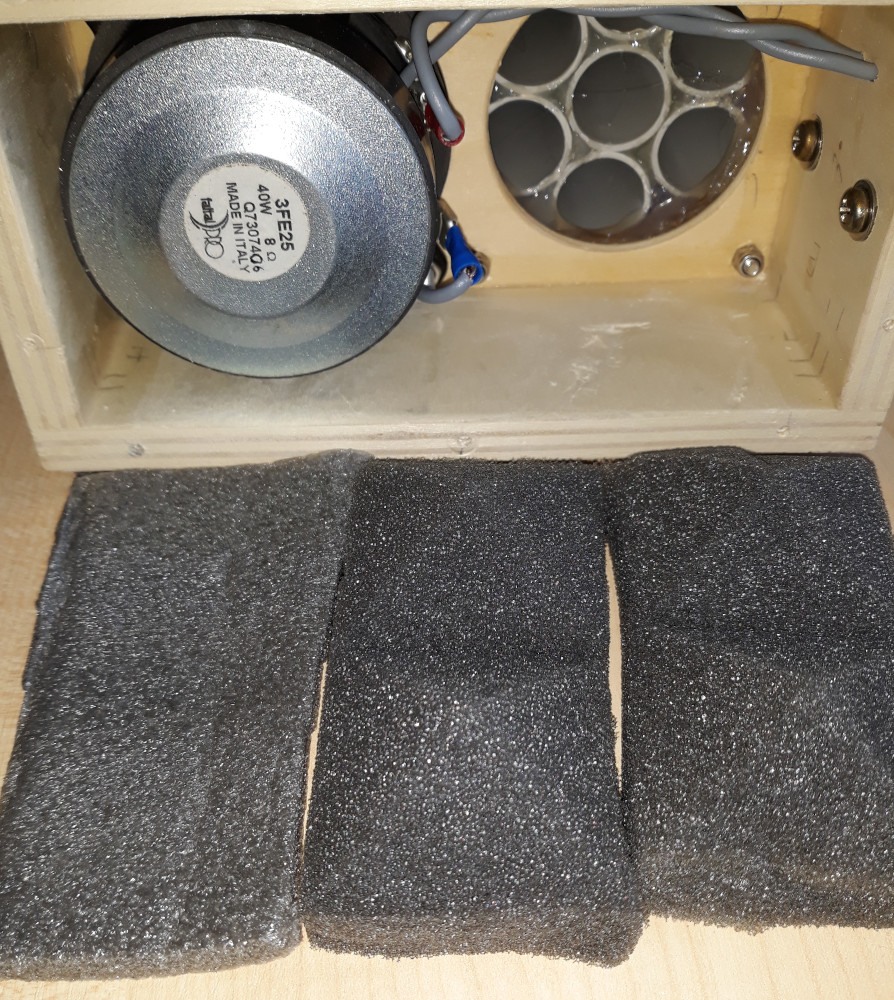
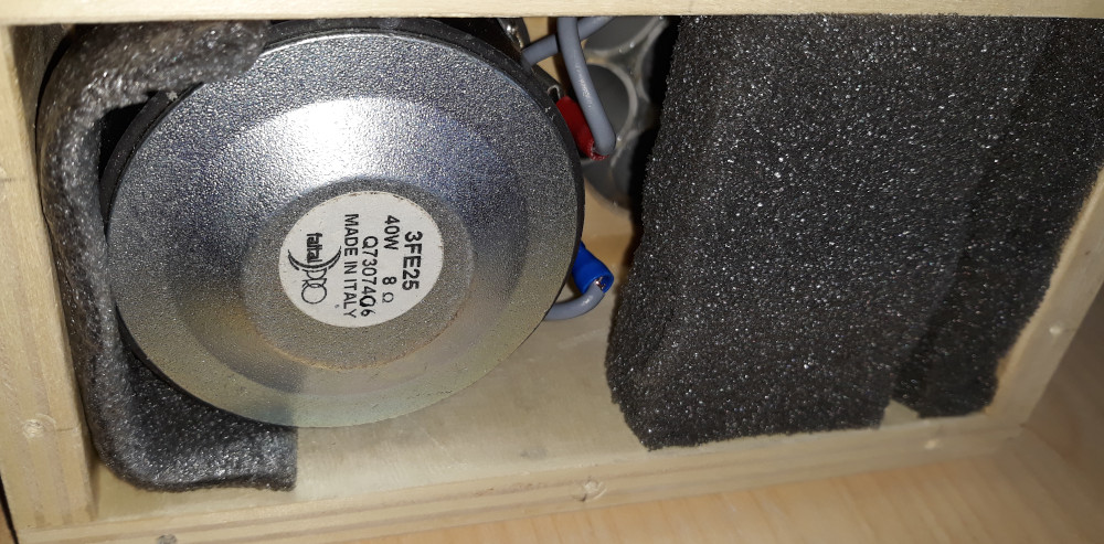
Nelle foto è visibile la camera di compressione del carico acustico posteriore senza e con materiale smorzante. A livello strumentale non riesco a rilevare differenze.
The photos show the compression chamber of the rear acoustic load without and with damping material. On an instrumental level, I cannot detect any differences.